
MAZDA Madness
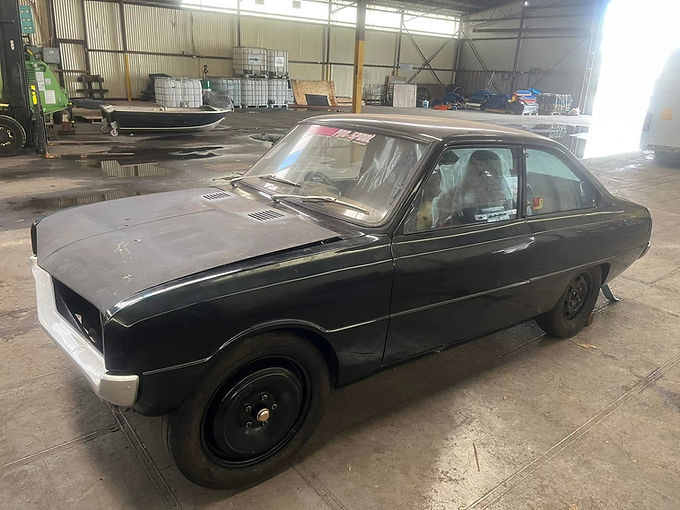
Aarons R100 sat around in other shops, pushed to the side waiting to be worked on for years before we took it on, the plan was a back half chassis, mono-leaf on coilovers, 9" diff with a billet turbo 13b, retain the rear seat and fit 20x10" Simmons on the back. Pretty simple build, until Aaron saw our other builds on the go and some of those ideas went out the window for something much wilder. We initially designed the rear clip to work with a slider rear mono-leaf and coilovers, raising the chassis a full 80mm above the old rear sub-frame and keeping it parallel from the front-subframe, basically creating a 3/4 chassis car tied into the front sub-frame and transmission x-member. But designing this rear clip had its challenges, mainly retaining the rear seat position and boot floor height. We design everything on CAD in-house, so reference points and measurements were drawn in for the original frame, floor height and seat positions. We ended up with a pretty radical design that retained the factory rear seat position and created a rear seat x-member that tied into the rocker panels and a k-design under the driver/passenger seat position which stiffens the front of the chassis into the front-subframe. CAD drawings shown below just of the chassis.


With all of our chassis designs, we opt for a 4-sided fabricated construction which allows us to make tighter radiuses and closer changes in direction over a conventional rolled RHS frame, with the biggest advantage being control and accuracy. Seen below is the tacking together stage of the frame rails, note the fish plates which have keyways along the entire span of the rails to keep them parallel and strong. The rails will be tig welded on all sides.


Shown below is the rails mocked up in the car, which was placed on our chassis jig. With only a small section of the floorpan and boot floor cut out to keep rigidity in the body before we cross-brace.


Rocker panels and c-pillars were cross-braced before the new rails were welded into the front sub-frame and rear x-member. The factory sub-frame, wheel tubs and boot floor were cut out, this will all be re-created once the chassis is all done.


Rear seat x-member and rocker plates and bracing being welded in. Note the hoop in the rear seat x-member replicates the original design which acts as a step for the base of the rear seat, this hoop was raised 40mm to accommodate the tail shaft at the new designed ride height.


The photo below shows the split mono-leaf design on the new rails. This is where the build dramatically changed..

Aaron had been following our other builds here and noticed how we design our vehicles here with airbags systems and 4 link suspensions, setting the ride height exactly where you want it with no compromise in ride quality. The consensus was we design an entire suspension system using airbags, adjustable shocks, adjustable 4-link rear with anti-roll for maximum suspension adjustability and that's just for the rear! Lets stick with the rear first before we dive into the front suspension. Onto the drawing board, we started designing this fully adjustable rear suspension into this tiny space.

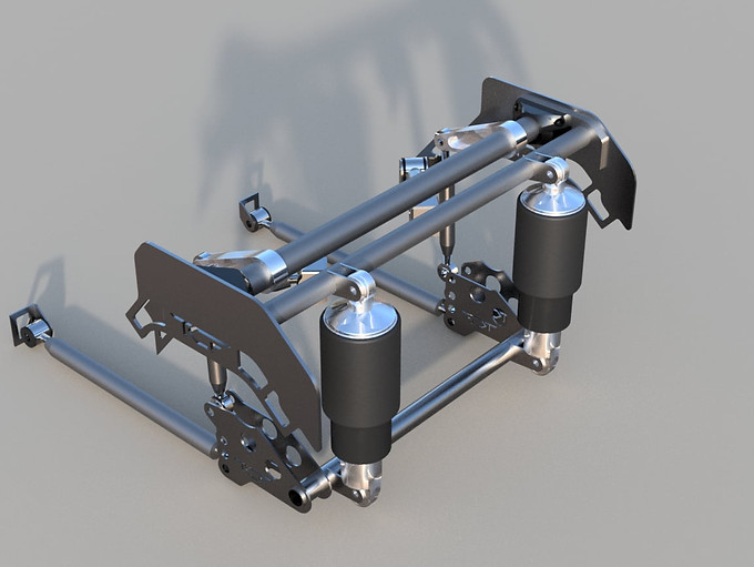
Some initial renderings shown above, using Ridetech Shockwave air-shocks, a tri-angulated 4-link system and an adjustable anti-roll. We also opted to replace the enormous braced 9" diff with a smaller fabricated Hilux floater diff from Race Products. All this had to fit under the floor, and work together in a tight space. Lots of componentry had to be designed just for this car. Final renderings shown below, and the advantage of using CAD systems is we can simulate the suspension movement up and down and under roll to ensure we have no binding or over-stressing on components.


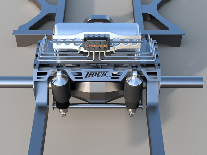
In the renderings you'll notice side-plates welded to the chassis, this will carry a bridge plate and also tie in a tube side to side which will pickup the top shock mounts. Final renderings below show the top bridge plate, which will carry the 3 gallon air-tank and air management system. Routing for air lines are also thought out and adapted into the design. Mounts for the tank and ECU shown below aswell.


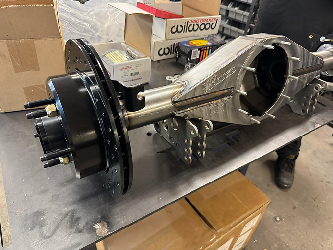
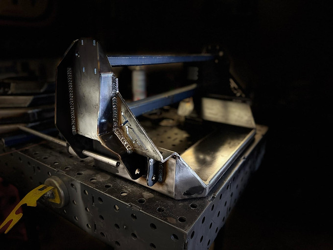
From CAD to reality, photos below showing the fabrication of the rear suspension and diff.


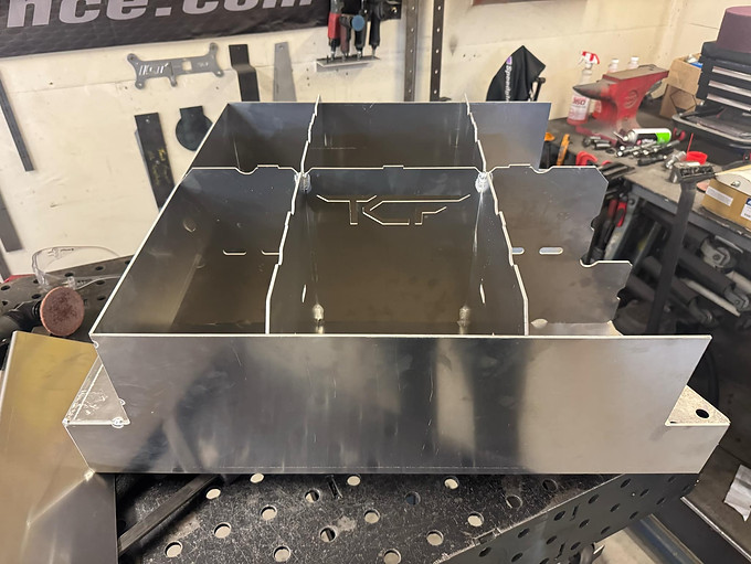
Once it was all welded in and mocked up, it was all removed and sent off to powder coat. In that time, we designed up the fuel tank. This we had planned from the initial chassis design months ago, we wanted it to be mostly under floor and about 40mm above chassis rails. Aaron already had a Fueled by AI fuel pump hanger which we used in the design. We were able to create a 78 Litre aluminium tank with internal baffles which extend under the chassis rails to give us even more volume. Side plates are used to bolt the tank to the chassis and carry the plate design up to the bridge plate.
.png)
.png)
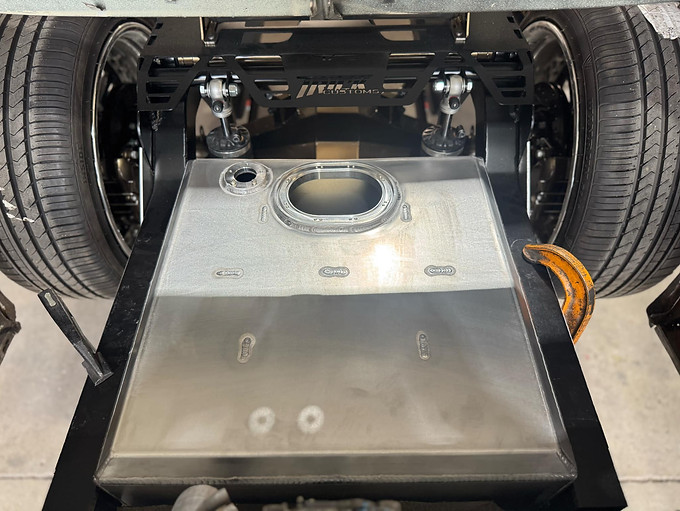
Design to reality.. tank being manufactured below. Fuel sender unit will be a Holley Lidar unit.


Parts coming back from powder coating and being installed in the car for an upcoming show.


After components were re-installed back into the car, the rear wheel openings were extended 40mm to house the enourmous 3-piece 20" Simmons.
Shown below is the aired out height of the rear, note the gap between the tire and the factory rear parcel shelf as this needed to remain for the factory rear seat. Aaron has the convenience of driving like this and still achieving a pinion angle in spec and also has the ability to air right up to 90mm above this height for speed bumps and driveways.


At this point we had to get the car ready for the Growl Racing Performance Pulse Expo for 2025, it was the first time the public were able to see our work on this car and the feedback was incredible. Some photos below of our stand at the event where we showcased it next to another one of our builds.


.jpg)

After the Expo, we got right onto the front end. We knew we had to start from scratch, as the geometry and space didn't allow the factory front end to drop enough in height to match the rear. Like the rear rails, reference points and measurements were taken while the car was on the jig (as this was planned when the rear suspension was designed).


We cant give too much away of our I.P. but we are using readily available ball joints and an aftermarket lowered stub axle with plenty of choice for brakes and stud patterns. Shocks/Bags will be matched to the rear with RideTech Shockwaves, our own bushes and cross-shafts and all this to be bolted into factory k-frame position. Engine was positioned and our front engine mount was designed and made.

We pre-loaded an amount of caster into the control arms with the ability to adjust. Camber and track width is also adjustable. Simulation shows suspension traveling from jounce to extension, which is a full 130mm at the wheel hub only changing 0.35deg of camber over the total travel.


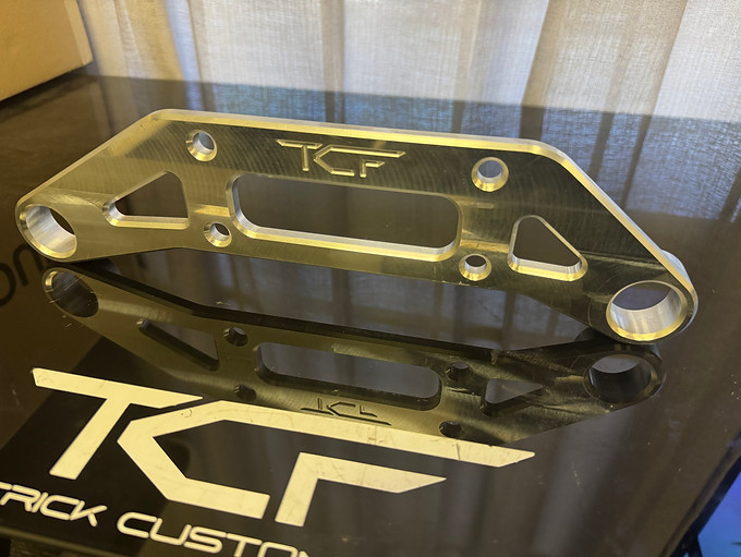
Photos below show the front end coming together. Cross-shafts and ball joint cups made.


Updated as of July 2025.